Prepare Your VoIP Network for Recording
When preparing to use VoIP, it is important to take into consideration the differences in how voice and call control information is handled in a VoIP network compared to a traditional wired network. The location of taps within your network determines whether Uptivity can record calls. Additionally, if you use mirror ports (also known as a SPAN port in Cisco environments) with passive VoIP, they have some limitations that can impact the configuration of your network.
Network Topology Considerations
On traditional wired telephone networks, all voice and call control information passes through a central location—the PBX![]() An acronym for Private Branch Exchange. A telephone switching device owned by a private company that serves a particular business or office.. Each channel on the network is tapped individually, and a single tap point obtains all voice data and call control information.
An acronym for Private Branch Exchange. A telephone switching device owned by a private company that serves a particular business or office.. Each channel on the network is tapped individually, and a single tap point obtains all voice data and call control information.
With VoIP networks, it isn't as straightforward, because only the call control information is guaranteed to pass through the VoIP-enabled PBX. Once call setup at the PBX is complete, voice packets are often routed along a different path from the signaling data, so IP networks may not offer a central location to tap all voice and call control information.
For example, incoming calls typically enter the external-facing, VoIP-enabled PBX. The PBX negotiates the call with the IP phone and voice packets pass directly to the phone once the call is connected. Positioning a tap for Uptivity between the router and each workgroup switch allows for capturing both control and voice packets.
In the case of peer-to-peer (internal) calls where both phones are on the same workgroup switch, the RTP![]() Real-time Transport Protocol (RTP) is a network protocol used in the transmission of audio and video data over Internet Protocol (IP) networks. voice packets are routed directly between the endpoints. Consequently, Uptivity would not record these calls, as the voice packets never leave the local subnet, and so do not reach the Uptivity tap.
Real-time Transport Protocol (RTP) is a network protocol used in the transmission of audio and video data over Internet Protocol (IP) networks. voice packets are routed directly between the endpoints. Consequently, Uptivity would not record these calls, as the voice packets never leave the local subnet, and so do not reach the Uptivity tap.
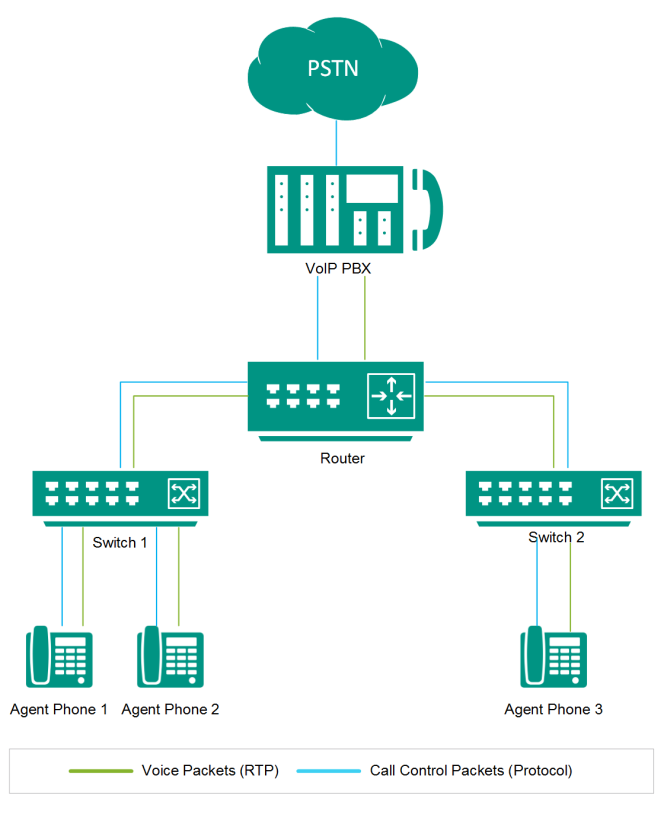
Ultimately, Uptivity can only process packets that it can see. If your organization wants to record all voice packets on the network (including agent-to-agent conversations), taps must be positioned deeper in the network. Depending on your needs, your inContact Sales Engineer may recommend positioning taps between phones and the workgroup switch, or may recommend relying on the switch’s mirror port.
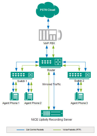
Passive Recording with Mirror Ports
When mirror ports are used, data packets processed by the switch are replicated and passed off the network via this specialized port. The mirror port is connected to the Uptivity recording server, which is capable of decoding signaling packets and processing RTP![]() Real-time Transport Protocol (RTP) is a network protocol used in the transmission of audio and video data over Internet Protocol (IP) networks. media.
Real-time Transport Protocol (RTP) is a network protocol used in the transmission of audio and video data over Internet Protocol (IP) networks. media.
Mirror Port Limitations
There are two significant limitations to tapping a VoIP network with mirror ports. First, capacity limitations can be reached which result in packet loss. When mirror ports are used, data from multiple ports on the switch is aggregated and passed on to a single port. Access to full-duplex traffic is constrained by the mirror port's capacity. If a single 10/100 Mbps port attempts to monitor multiple 10/100 Mbps ports, data packets are dropped when the mirror port reaches its capacity.
Many switch manufacturers now design mirror ports with larger capacities to compensate for this. You and your inContact Sales Engineer should work together to determine the capacity of mirror port(s) on your system before assuming a single port can handle the traffic load.
The second consideration is the inherent design of the switch itself. In normal usage, the switch moves all network traffic. With packet mirroring, the switch has the added responsibility of duplicating packets passed to the mirror port. This added burden to the switch’s processors impacts its performance. Some switch manufacturers, such as Cisco, build safeguards into their products which result in the switch giving a lower priority to mirrored data.
In other words, if any resource under load must choose between passing normal traffic and mirrored data, the normal traffic is passed and the mirrored frames are arbitrarily discarded. When the network is running at high capacity it can overload the switch. As a result, packet loss can occur even if the switch is designed with a gigabit mirror port.
Ultimately, the best design is a tapping solution that reduces processing needs placed on the switch and minimizes load on the mirror port. This type of system design reduces potential for packet loss. Depending on the capabilities of the switch, one or more of the following configuration options are recommended:
- Eliminate traffic from ports not connected to VoIP endpoints.
- Distribute packets across multiple mirror ports.
Eliminating Traffic and Unnecessary Packets
This approach considers the types of devices connected to each port. Many devices send data packets across the network, such as printers, but Uptivity is not interested in data packets like these. Eliminating this kind of traffic helps reduce the number of packets lost due to overloaded switches. To eliminate this kind of traffic, only the ports connected to employee work stations equipped with a VoIP phone should be mirrored.
Most switches can be configured to enable mirroring control on a port-by-port basis. As a result, only the data packets of specified ports are replicated and pushed into the mirror port. This reduces the overall load placed on the switch while at the same time reducing the potential of reaching the mirror port’s capacity.
It is important to understand the control options supported by your switch model. Some switches allow users to select mirroring options based on a virtual LAN (VLAN). In this case, all ports assigned to a single VLAN are mirrored. Other models allow configuration based on individual ports.
Ultimately, the best design is one that eliminates unnecessary packets and limits the total number of packets being duplicated. While this is an effective strategy, it is important to remember that local networks can change (for example, a printer can be removed from a port and a phone can be added).
Distributing Packets
A tapping solution can be designed using a single switch with multiple mirror ports. Distributing traffic across multiple ports is an effective method when working on high-density networks. In this scenario, traffic from a few ports is duplicated to one mirror port, while the rest of network traffic is mirrored to another port.
This design option does not protect the processing needs of the switch, but it does reduce the load on each mirror port. This option is only available if the tapped switch supports multiple mirror sessions. Additionally, your Uptivity hardware solution will require a NIC![]() A Network Interface Card (NIC) is a hardware device added ti a computer that enables it to connect to a network. per mirror port, which may incur additional hardware costs.
A Network Interface Card (NIC) is a hardware device added ti a computer that enables it to connect to a network. per mirror port, which may incur additional hardware costs.
Mirror Port Guidelines and Best Practices
Before designing a tapping solution that relies on mirror ports, it is imperative to evaluate whether the port’s capacity is large enough to handle all of the packets. Consider these guidelines in evaluating your mirror port(s):
- A single 10Base-T is considered to be running at full capacity when network rates reach about 6-7Mbps (60-70%). If this limit is breached, errors can be noted due to collisions. Most corporate networks are designed with this in mind.
- On low traffic networks, where each port remains at 10-20% capacity (1-2Mbps), a single 10Base-T mirror port is capable of monitoring a total of three ports (a total of 3-6Mbps of traffic). To monitor more ports, a 100Base-T mirror port is required.
- The same rule applies with a 100Base-T switch. If three ports are monitored, each running at 10-20Mbps, the total amount sent to the mirror port would be approximately 30-60Mbps. This is the maximum load that should be passed to the mirror port without risking packet loss. For high-capacity networks, multiple mirror ports should be used, with each connected to a single monitoring component.
- Where possible, mirror only the received (Rx) packets from each device/host on a port for individual phone ports. Add a second mirror for only the Rx packets from each switch gateway that passes RTP
 Real-time Transport Protocol (RTP) is a network protocol used in the transmission of audio and video data over Internet Protocol (IP) networks. and control packets. This will result in mirroring both sides of the conversation without duplicating traffic.
 - Mirroring both transmitted (Tx) and Rx packets on all ports is not advisable unless you do not intend to monitor the PBX endpoints. Otherwise, you will duplicate all the traffic since you will set it at both the phone and PBX taps.
- In most cases, VLAN mirroring is preferred to individual port mirroring. VoIP traffic is normally passed on a separate VLAN, so this is usually easiest to implement. On Cisco devices, this also allows you to use RSPAN to span the same VLAN on multiple switches. There is usually a limit to the number of individual ports you can mirror, so VLAN spanning may be the only way to capture traffic from all required ports. Uptivity supports recording tagged VLAN traffic.
Common Mirror Port Issues
- Mirroring only one direction—Some switches only support mirroring one direction (Transmitted or Received) on an interface. This can be overcome by deploying an aggregator or by using the Windows operating system to bond together multiple NICs (in other words, transmit on one NIC and receive on another).
- Packet duplication—Uptivity has the ability to turn on a packet filter to eliminate duplicate packets, but this can impact performance on the recording server. inContact therefore recommends eliminating packet duplication as much as possible.
- Not mirroring all phone-to-phone traffic—When not all phone-to-phone traffic is mirrored, audio will be missed in some scenarios. This commonly occurs on larger distributed networks.
- Saturating the mirror port—Exceeding the interface’s bandwidth rate limit causes missed audio and call events. The result can be gaps in audio, recordings that run together, or both. To overcome this issue, split off network segments to multiple switches and use an aggregator or multiple NICs.
Effects of NIC Type on Mirror Port-Based Recording
Uptivity relies on the Windows operating system to provide data from any network interface. Thus, the application should be able to monitor traffic from any interface that can run in promiscuous mode. If the Windows operating system treats the device as a standard network interface, Uptivity can interface with the NIC and record the network traffic.
NICE Uptivity has been used successfully in bonded NIC environments, where two interfaces are bonded together on the Windows server. Bonded NICs are commonly deployed to aggregate transmit and receive traffic. Uptivity has also successfully recorded fiber-based network interfaces.
Virtual machines and VMWare applications typically do not allow for an interface to be accessed in promiscuous mode. Due to limitations and inconsistencies in the performance of these platforms, Uptivity does not support passive VoIP recording in a virtualized environment.
Passive Recording with Hardware-Based Network Taps
inContact has partnered with DataCom Systems to provide customers with a physical, hardware-based tapping solution. These hardware devices can be passively injected into a network environment (for example, in between a PBX uplink port and a network switch). DataCom also has data aggregation units available if multiple tapping points are required.
These solutions vary in complexity and deployment configuration but are an option for organizations that are unable to or prefer not to use port mirroring. For more information on hardware-based network taps, ask your NICE Uptivityteam.
|
|
|


